The Installations tool contains blocks of building services that you place on the plan: electrical, HVAC and plumbing connection points, and the north arrow. SquarePlan uses them to generate the installation designs and bills of quantities for the fit-out cost estimate. This tool is optional, but some estimates need specific blocks, for example at least one switchboard for electrical installations.
How to place installation blocks
- Select the Installations tool in the Structure & Design panel.
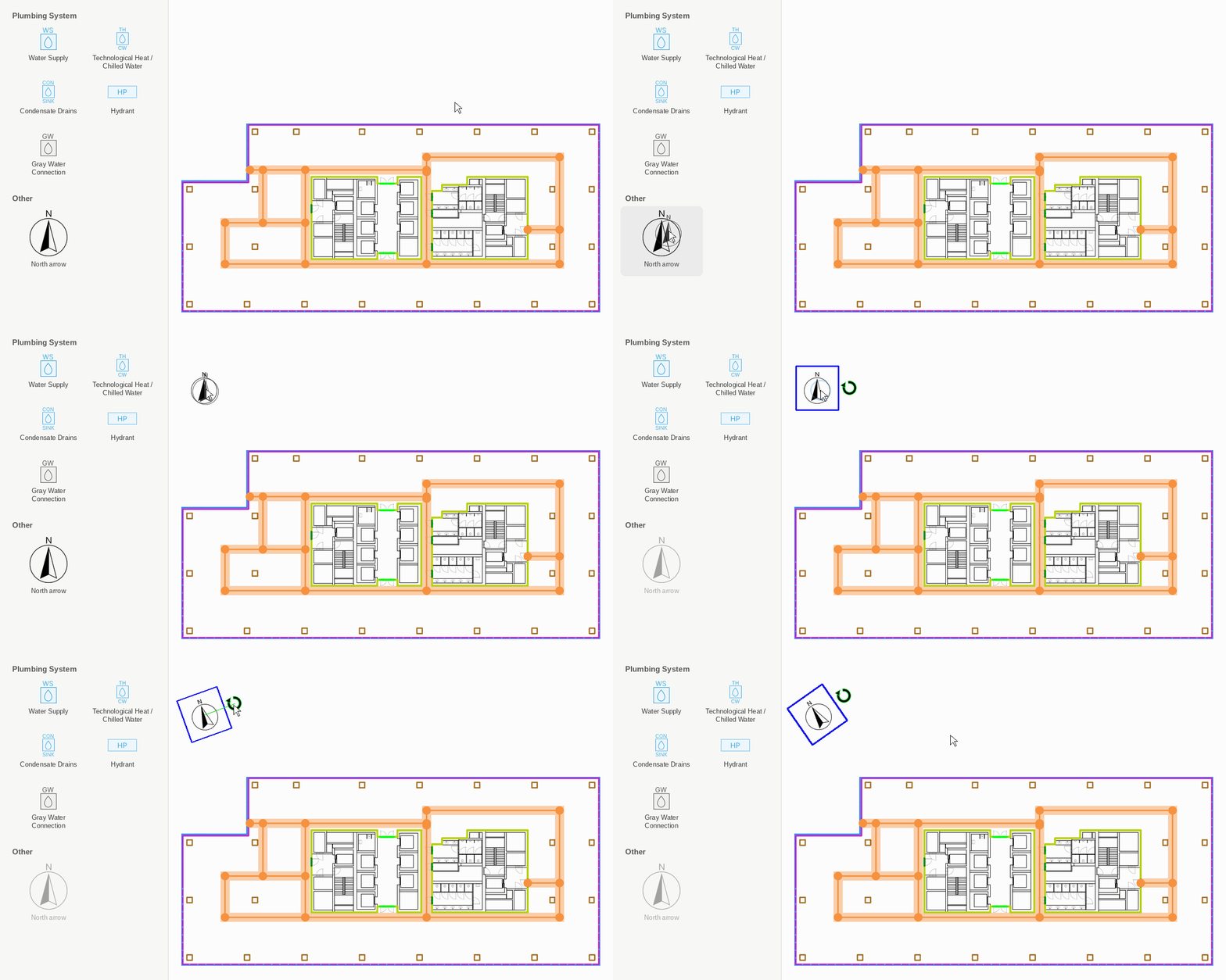
- In the Installations panel, choose the block you need. Blocks are grouped into Electrical System, HVAC System, Plumbing System and Other. The block icon now follows your mouse cursor.
- Click on the plan to place the block at the location of the existing or designed element.
Rotating a block
- Press Esc to exit the tool.
- Select a placed block. It is highlighted with a frame, and a rotate handle appears next to it.
- Drag the rotate handle with the mouse to set the angle. The angle is set only with the mouse; you cannot type in a value.
Changing the airflow capacity of HVAC blocks
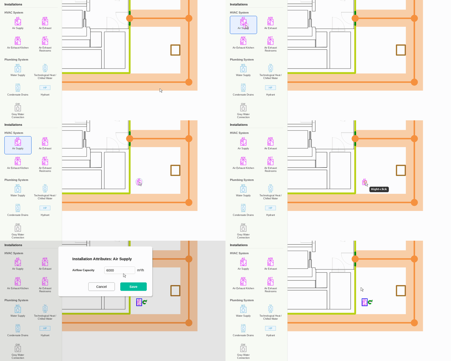
For HVAC blocks (Air Supply, Air Exhaust, Air Exhaust Kitchen and Air Exhaust Restrooms) you can change the Airflow Capacity attribute, which is the capacity of the shaft or duct the block represents. The default value is 2,500 m³/h per block.
- Press Esc to exit the tool.
- Right-click the installation block on the plan.
- Choose Edit attributes from the menu.
- In the Installation Attributes window, enter the new value in Airflow Capacity (m³/h), for example 7000.
- Click Save.
Electrical System
Icon | Block | How to use it |
 | Rack cabinet | Place it where the rack cabinet is planned, inside the arrangement area or outside it in a room in the building core. If the room with the rack cabinet is inside the arrangement area, the software automatically assigns an antistatic PVC floor finish to the server room and plans slab-to-slab walls around it. In Designer you can also add gas fire suppression for this room: Cost estimate → Technical specification → Basic view → Server room. |
| Switchboard | Place it where the electrical switchboard is planned, inside the arrangement area or outside it in a room in the building core. At least one switchboard is required to generate bills of quantities for electrical installations and some other trades. |
| Fire Alarm System | Place the fire alarm (FAS) switchboard according to the existing layout, for example in a technical room next to the electrical switchboard in the core. |
| Voice Alarm Systems | Place the voice alarm (VAS) switchboard according to the existing layout, for example in a technical room next to the electrical switchboard in the core. |
| CCTV Camera | Place the cameras in the arrangement area according to the existing or designed layout. |


HVAC System
Icon | Block | How to use it |
| Air Supply | Marks the point from which the office supply air installation is routed automatically. Depending on the scope and the existing layout, this can be a supply duct at the edge of the arrangement area, for example in a core wall, or a supply riser in a building shaft. The default capacity is 6000 m³/h per block. |
 | Air Exhaust | Marks the point to which the office exhaust air installation is routed automatically: an exhaust duct at the edge of the arrangement area or an exhaust riser in a building shaft. The default capacity is 6000 m³/h per block. |
 | Air Exhaust Kitchen | Marks the point to which exhaust air from kitchenettes and coffee points is routed automatically. The default capacity is 1000 m³/h per block. |
 | Air Exhaust Restrooms | Marks the point to which exhaust air from restrooms is routed automatically. The default capacity is 1000 m³/h per block. |
Plumbing System
Icon | Block | How to use it |
| Water Supply | Marks the location of the water connection. This installation is currently not included in the automatic MEP designs. |
| Technological Heat / Chilled Water | Marks the connection point for chilled water and technological heat. |
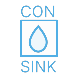
| Condensate Drains | Marks where condensate from the air conditioning system is drained. |
| Hydrant | Marks existing or designed hydrants. The software adds hydrants where they are needed, based on their coverage range. |
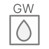
| Gray Water Connection | Marks existing gray water drains. If a drain is more than 40 m from a fixture such as a sink or washbasin, a sewage pump is added. |

Other
Icon | Block | How to use it |
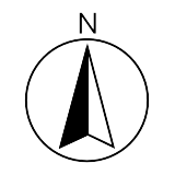
| North arrow | Rotate the arrow with the rotate handle so that it points north relative to the plan. The compass directions are taken into account when the air conditioning design is generated. |
Czy ten artykuł był pomocny?
To wspaniale!
Dziękujemy za opinię
Przepraszamy, że nie udało nam się pomóc!
Dziękujemy za opinię
Wysłano opinię
Doceniamy Twój wysiłek i postaramy się naprawić artykuł